Radio and Test Equipment Projects and Restorations
This page contains a listing of both current, and past, radio and test equipment projects I have, or am presently, engaged in. As I begin, and work through, a particular restoration or repair, I will try to maintain a complete log with photos of my progress, my successes and triumphs, and hopefully few missteps and blunders. My reasoning for doing this is twofold: First, it will chronicle for posterity (at least till I croak, at which point I figure my daughter and wife will erase my hard drive and throw away the paperwork, let the website lapse, and yardsale my collection) my efforts on the various radios and devices I work on, and help me to recall my approach to specific problems, and record improvements on techniques. Secondly, I feel it could be a valuable learning resource for those who wish to read and study how others attack their restorations, and possibly prevent them from making the same mistakes and errors.
Clough Brengle Model OM Frequency Modulator
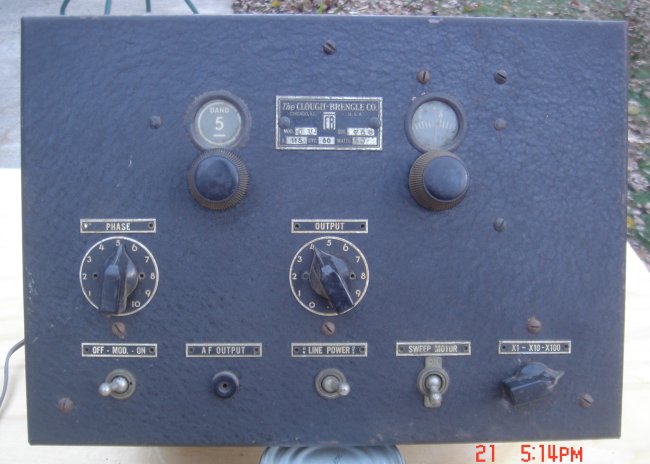
The Model OM was the first attempt by Clough Brengle at marketing a combined signal generator and frequency modulator in one case. Produced from about 1935 until 1937 when it was replaced by the model OMA, the OM introduced to the radio serviceman the ability to inject a discrete frequency modulated AM signal into a radio receiver, and use that signal to accurately diagnose problems with the newly introduced oscillographs as the output device. This particular unit, serial number 758, was purchased by me on Ebay in December of 2007, proved to be in pretty sad condition when received.
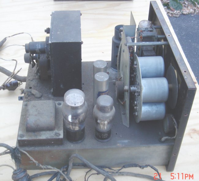
Here we see the OM with the case removed. Note the extreme amount of dust and grease build-up on the chassis, especially near the variable inductor fan motor at the rear (directly below the metal 6C5 tube). Seventy plus years of oil being applied to the motor shaft, and dripping down onto the top of the chassis has made for a rather gooey mess. Also note the condition of the power cord and test leads. All of these lines will of course have to be replaced. This shot also shows the "Roto-Inductor" unit, which by even this early date Clough Brengle was famous for. Essentially a rotating plate with a number of individual tank circuit coils corresponding to the number of frequency bands available, C-B was able to say that the mechanism: "Eliminates the losses and calibration destroying effects of band-switches with their multiplicity of leads. Instead, each coil is 100% shielded by metal and rotated into the circuit, using less than four inches of lead for the entire coil circuit connections." The design worked so well, C-B used it, with variations, on all subsequent signal generators until production ceased sometime in the late 1950's."